
Efficient Workflow
with Allplan Bridge
Code-based design
Once the global effects are calculated and the relevant envelopes have been created the user can perform code dependent design tasks to determine the required reinforcement content. After the reinforcement area has been calculated or manually specified, the design code checks can be performed according to Eurocode and AASHTO LRFD.
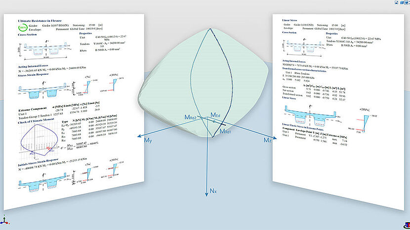
For ULS checks of flexural capacity a 3D interaction surface of the section resistance is calculated. Intersecting this surface with the relevant internal moment vector MRes gives the user the detailed information on the level of capacity utilization. EN design for shear is based on the variable-angle truss model. The torsional resistance of a section is calculated based on an equivalent thin-walled closed section. The cross-section parts effective for the resistance in shear and torsion are automatically defined based on linear elastic shear stress distribution due to unit loads Qz, Qy and Tx. The effects of all components of internal forces may be superimposed and the interaction of N, My, Mz, Vy, Vz, and T can be checked.
As concerning the EN code assessments, the serviceability conditions are often governing the cross-section design. Normal stresses and crack width due to service effects are calculated assuming the concrete ineffective in tension. The EN crack width approach is extended into an innovative general method suitable for real-life bridge cross-sections. Arbitrarily shaped reinforced cross–sections are converted into local cracking zones, in which the area of effective embedment is determined. At the same time bar strain calculation takes account of full section geometry.
Design and check features are also available for the AASHTO LRFD 9 version of the standard. All design situations automatically apply corresponding resistance factors Φ. The strength limit state is covered for flexural capacity, shear and torsional resistance as well as for their interaction as one complex loading of the section. The service limit state is covered for stress limitation and crack control. The fatigue limit state is checked to prevent fracture during the lifespan of the modeled bridge. In addition to that, the minimum reinforcement area design/check was added to ensure the prevention of brittle failure. Each design situation respects several detailing rules for longitudinal reinforcement, transverse reinforcement, and tendons.
- Code dependent design of reinforcement area
- Design checks for prestressed and/or reinforced sections
- Considering the effects of creep, shrinkage and relaxation
- 3D Interaction diagram/surface


