New precast bridge in the Ahr Valley: Structural analysis with ALLPLAN Civil
A spectacular piece of alpine infrastructure is currently under construction on Lake Lucerne. The project stakeholders are tackling the numerous challenges with a fully model-based planning approach.
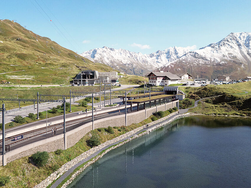
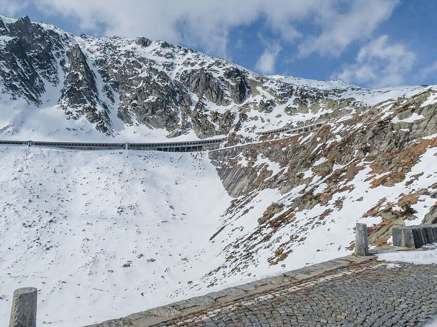
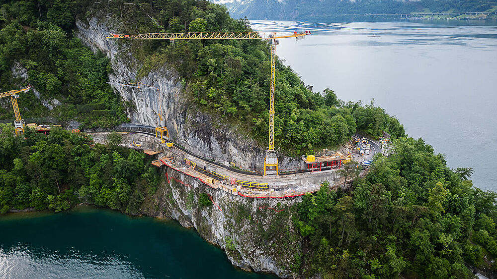
If you've ever driven through the Alps, you’ve likely seen them: roads that cantilever dramatically from rock faces they must cling to. One such retaining structure is part of a current road construction project on Lake Lucerne. A 400-meter-long section of the important cantonal road K2b between the towns of Vitznau and Gersau is being renovated and expanded. Of this, 313 meters are being constructed as a retaining structure. The demanding design for this striking structure was developed by Zurich-based engineering firm Bänziger Partner, primarily using ALLPLAN Civil. The formwork, reinforcement, and anchoring of the structure, the excavation pit including stabilization, the challenging terrain and subsoil, a high-voltage power line, and an existing bunker facility were all modeled.
Challenging Topography
The project, located on the border between the cantons of Lucerne and Schwyz, involves not only renewing the existing road (built in 1885/86 and last widened in 1939), but also adapting it to current standards. This results in a significant widening of the structure – with an increase in cantilever of between 3 and 5.5 meters. A major challenge is the topography: the road winds around the Rigi mountain massif and is the only connection between Vitznau and Gersau. A long-term road closure is therefore not an option, meaning construction must proceed under live traffic. The only exceptions are two full closures of three weeks each for work that cannot be carried out under traffic conditions. The road section is also situated in a highly exposed position above the lake, triggering strict landscape protection requirements for a visually appealing design. For example, the supporting structure is intended to resemble an organic form.
 Copyright: Bänziger Partner AG, Zurich
 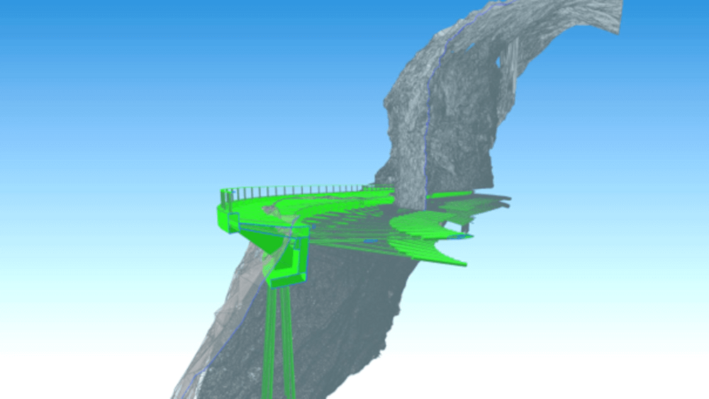 Copyright: Bänziger Partner AG, Zurich
  Copyright: Bänziger Partner AG, Zurich
 Three Different Structural Systems for One Retaining Structure
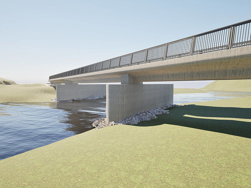
Given the topographical conditions, aesthetic requirements, and the need to build under traffic, only a back-anchored ribbed structure was feasible – one that is “squeezed” between the single-lane traffic route and the drop-off. The structure consists of a continuous strip foundation with a standard width of two meters, a continuous rear wall with a height of 3.5 meters, and permanent back anchoring using prestressed control anchors. The latter consists of strand anchors with seven 0.5-inch strands each, spaced one meter apart and drilled alternately at inclinations of five and 15 degrees.
Due to the high aesthetic demands, the ribs are spaced relatively closely at just four meters apart. The road deck extends lakeward to a cantilever head and supports the full pavement structure. The structure adapts continuously to the terrain and the planned road alignment. All 55 ribs have different geometries. In sections where the structure is partially concealed by forest, conventional retaining walls carry the roadway instead. In total, three different structural systems are used. Architect Eduard Imhof provided design support to the engineering team.
Another special feature is found midway up the rock face: a rock cut that the structure must bridge freely over a 20-meter span. Here, four ribs are supported by a reinforced rear wall, complemented by a road deck suspended on the mountain side. The strip foundation acts as a bottom chord and ensures high flexural stiffness.
 Copyright: Bänziger Partner AG, Zurich
 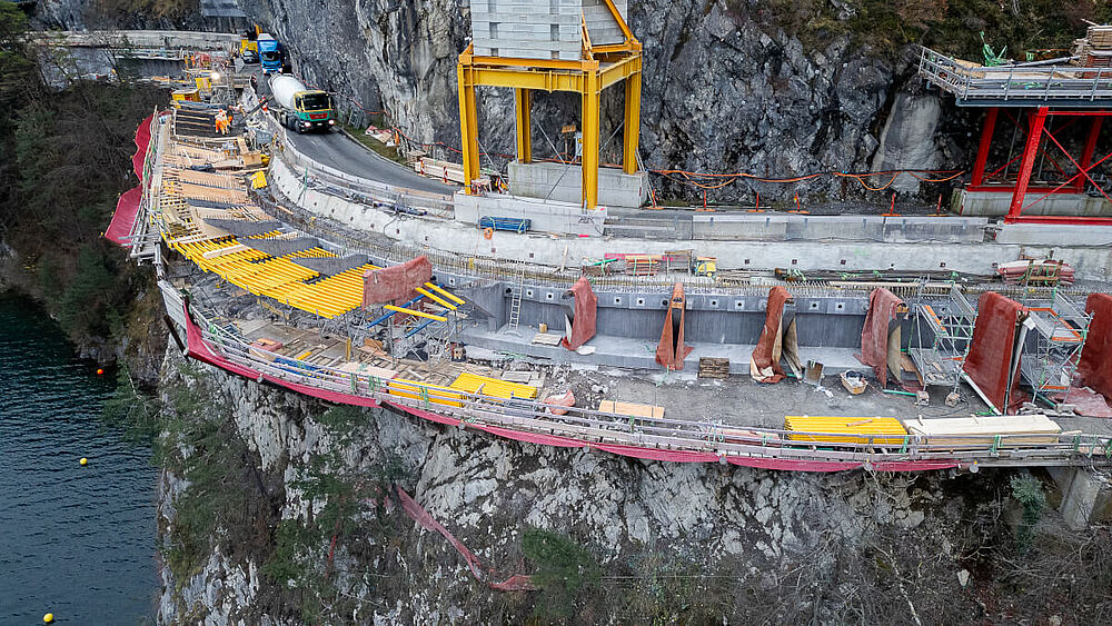 Copyright: Bänziger Partner AG, Zurich
 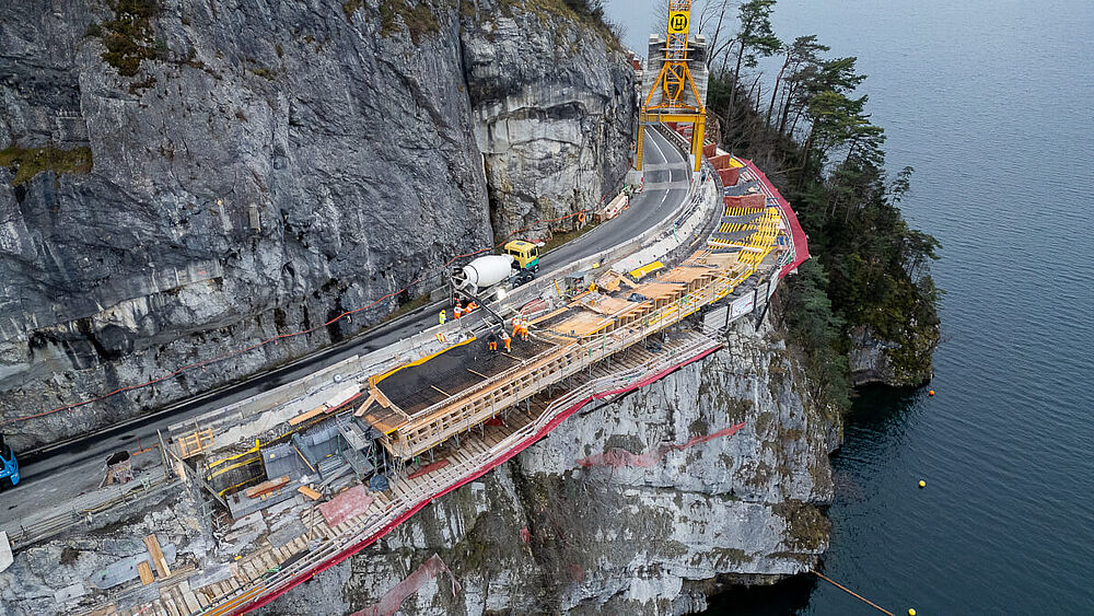 Copyright: Bänziger Partner AG, Zurich
 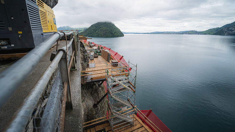 Copyright: Bänziger Partner AG, Zurich
  Copyright: Bänziger Partner AG, Zurich
 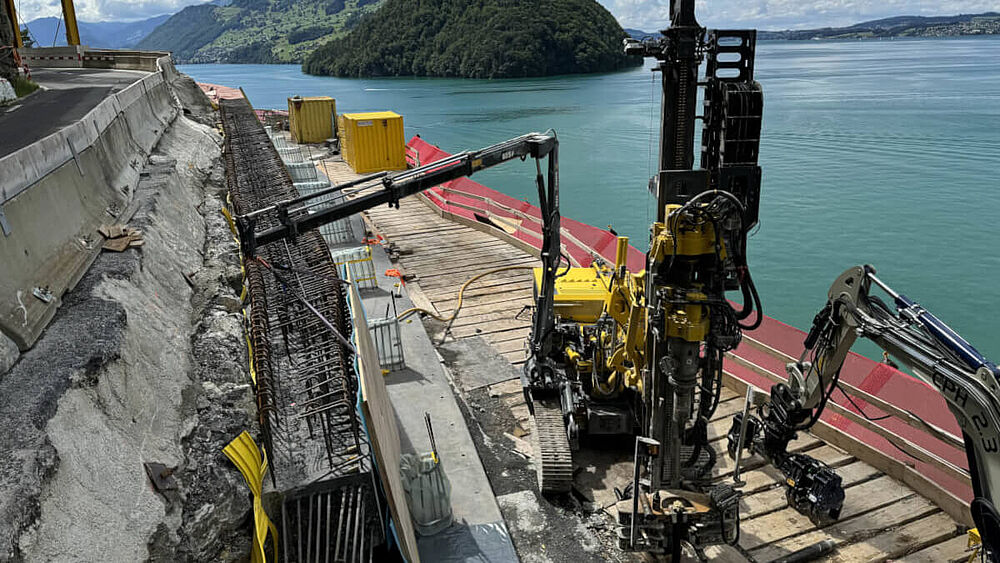 Copyright: Bänziger Partner AG, Zurich
 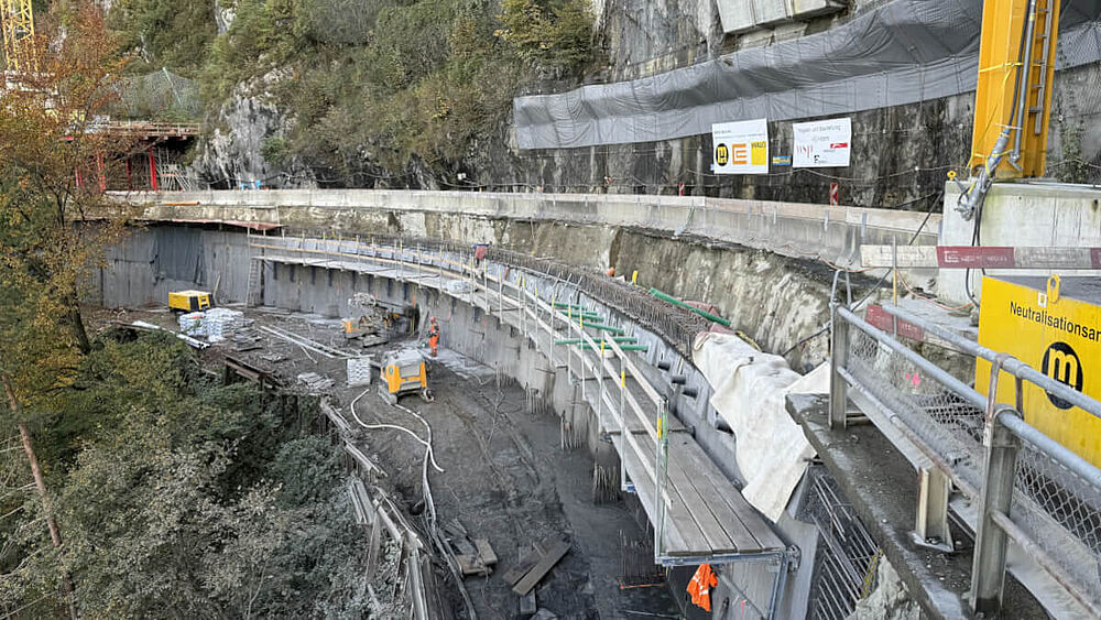 Copyright: Bänziger Partner AG, Zurich
 Fully Model-Based Planning with ALLPLAN
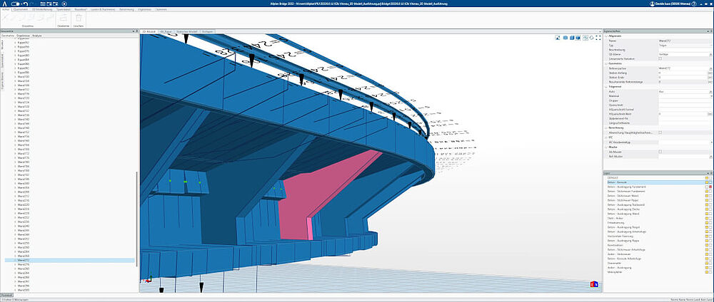
The design was based on a parametric model in ALLPLAN Civil. Bänziger Partner modeled not only the concrete structure but also all permanent non-prestressed and prestressed anchors, as well as the micropiles. Every component was assigned attributes such as name, length, inclination, etc. Due to the strong curvature of the structure, anchor crossings were unavoidable. Modeling made it easy to identify and avoid collisions. In addition to the structure, the excavation pit was also modeled so that the construction company can use 3D excavator control for the excavation. The excavation model includes all non-prestressed anchors used for temporary pit stabilization, allowing potential drilling conflicts to be identified during the planning phase.
Models were also created for other relevant objects, such as the existing bunker facility, the high-voltage line, and the terrain (including geology, rock surfaces, and fracture bodies), resulting in a fully model-based planning approach. According to the tender, even the contractor was required to create all construction site concepts in 3D – for example, to identify clashes between crane foundations and planned anchors, or between the heavy-duty scaffolding on the valley side and the micropiles. Bänziger Partner’s detailed BIM model thus already formed the basis for ensuring the feasibility of the project during the tender phase.
Overall, the increased planning effort required by the model more than paid off. For example, the complex reinforcement could be created based on the model, and temporary construction measures could be reviewed quickly and easily. The construction company also used the BIM model for model-based staking out, 3D excavator control, determining concrete volumes, and for continuously monitoring the excavation surface.
 Copyright: Bänziger Partner AG, Zurich
 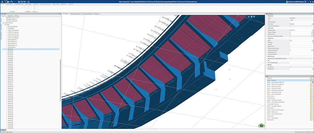 Copyright: Bänziger Partner AG, Zurich
 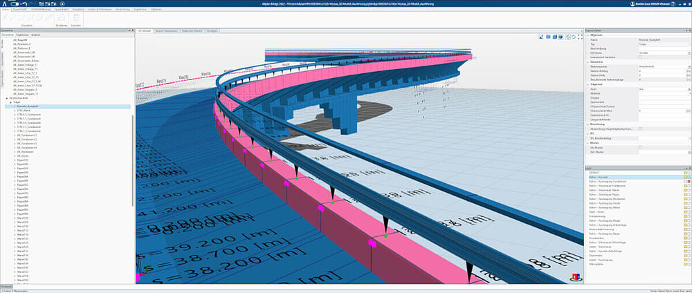 Copyright: Bänziger Partner AG, Zurich
 Project Participants
Client: Planning and Construction Management: Architectural Support: | Geology: Environmental Planning: Construction Execution: |