Upon completion in 2026, the courtyard development will provide affordable and future-proof living space for the citizens of Traunstein. Fifty new rental apartments, some of which will be income-subsidized, are being built in the new development area. Two engineering firms commissioned with the approval and implementation planning provide insights into their work processes and the software tools used for planning the excavation pit and the four solidly constructed apartment buildings.
How does a large district town succeed in setting an example for future-proof, multi-generational living? One way is through attractive, affordable, and barrier-free living space. In the Seiboldsdorf development area in the south of Traunstein, a residential quarter with 50 one- to five-room rental apartments is therefore being built, 33 of which are intended for citizens of Traunstein with low and middle incomes. This is made possible by the income-oriented subsidy (EOF) from the Free State of Bavaria, which grants low-interest loans for the construction of new apartment buildings through BayernLabo. In addition, the four-sided courtyard, which consists of four apartment buildings with underground parking, is planned according to ecological and social criteria in accordance with the KfW40 standard. Heat pump technology and a photovoltaic system are planned, as are a communal garden and a neighborhood café to promote social interaction. As the developer, the Traunstein housing association is thus fulfilling its mission of ensuring a secure, ecological, sustainable, and socially responsible housing supply for broad sections of the Traunstein population.
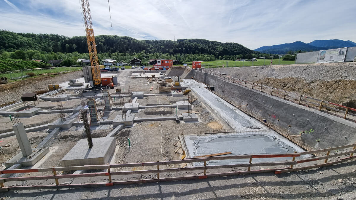
Construction details of the excavation pit
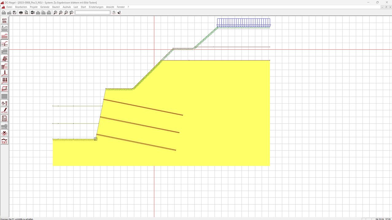
The excavation pit dug for the residential complex could be cut back to a self-supporting angle along the entire north and east sides without intermediate berms. However, because a stormwater basin had already been completed before construction began and an access road was already in place, shoring was required along the west and south sides of the excavation. GSGE GmbH, a regional geotechnical engineering firm specializing in deep foundations, designed the excavation shoring as a 10:1 inclined shotcrete soil nail wall. The soil-nailed walls were designed as a temporary safety measure. In order to account for the earthwork quantities, the office's draughtsman drew the excavation shoring plan in 3D using ALLPLAN.
Geotechnical design with DC software
Due to the depth of the excavation, Frédéric Gelloz, owner of GSGE GmbH, verified the stability of the excavation slopes using the DC-Böschung analysis program from DC Software, in accordance with DIN 4124. When designing the six-meter-high shoring with DC-Nagel, a partial soil replacement layer 0.6m thick was assumed below the base of the foundation slab. The calculations were performed in line with the partial safety concept of Eurocode 7, applying the limit states defined in EB 78 EAB and EC7. Verification was carried out for both the ultimate limit state and the global stability (slope failure) limit state. “I enjoy working with DC software because it allows me to obtain comprehensible results quickly and reliably. As an engineer, it is important for me to understand what the software is calculating in the background. DC makes it possible to perform validation checks, and it provides a solution for all my geotechnical design needs,” praises Gelloz, who has been working with DC since 2009. “For me, there is nothing better,” he emphasizes.
Construction details of the apartment buildings
The basement floors are built on a 35cm thick floor slab. The underground car park was designed by the Traunstein-based engineering firm concon, which was responsible for the structural engineering, building physics, and execution planning. The car park features a sloped paved parking area with individual and strip foundations. The ground floor cantilevers over the underground car park, which made it difficult to determine a clean static load transfer. The four apartment buildings are designed in traditional solid masonry construction. Each building is supported and structurally secured by reinforced concrete ceilings and masonry walls. When selecting the types of masonry and concrete to be used, the planners opted for a diverse selection in order to meet energy efficiency requirements. In addition to standard concrete, waterproof concrete is also used in some places. The roof structure was designed as a 28° pitched gable roof covered with tiles. The attic floors will be constructed using timber frame construction. The apartments will be accessed via pergolas, which will be built entirely from prefabricated parts without cladding. The non-load-bearing wooden cladding of the façades gives the four apartment buildings an attractive wooden look that is typical of the regional architecture.
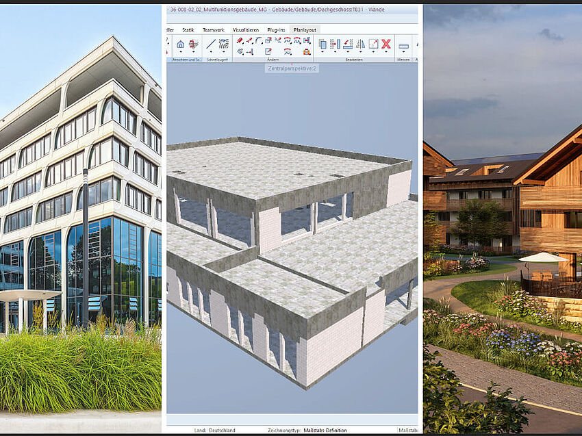
Creation of a structural engineering model
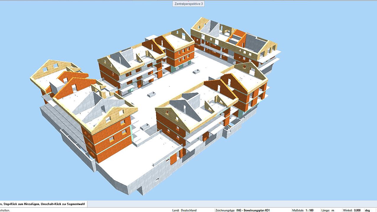
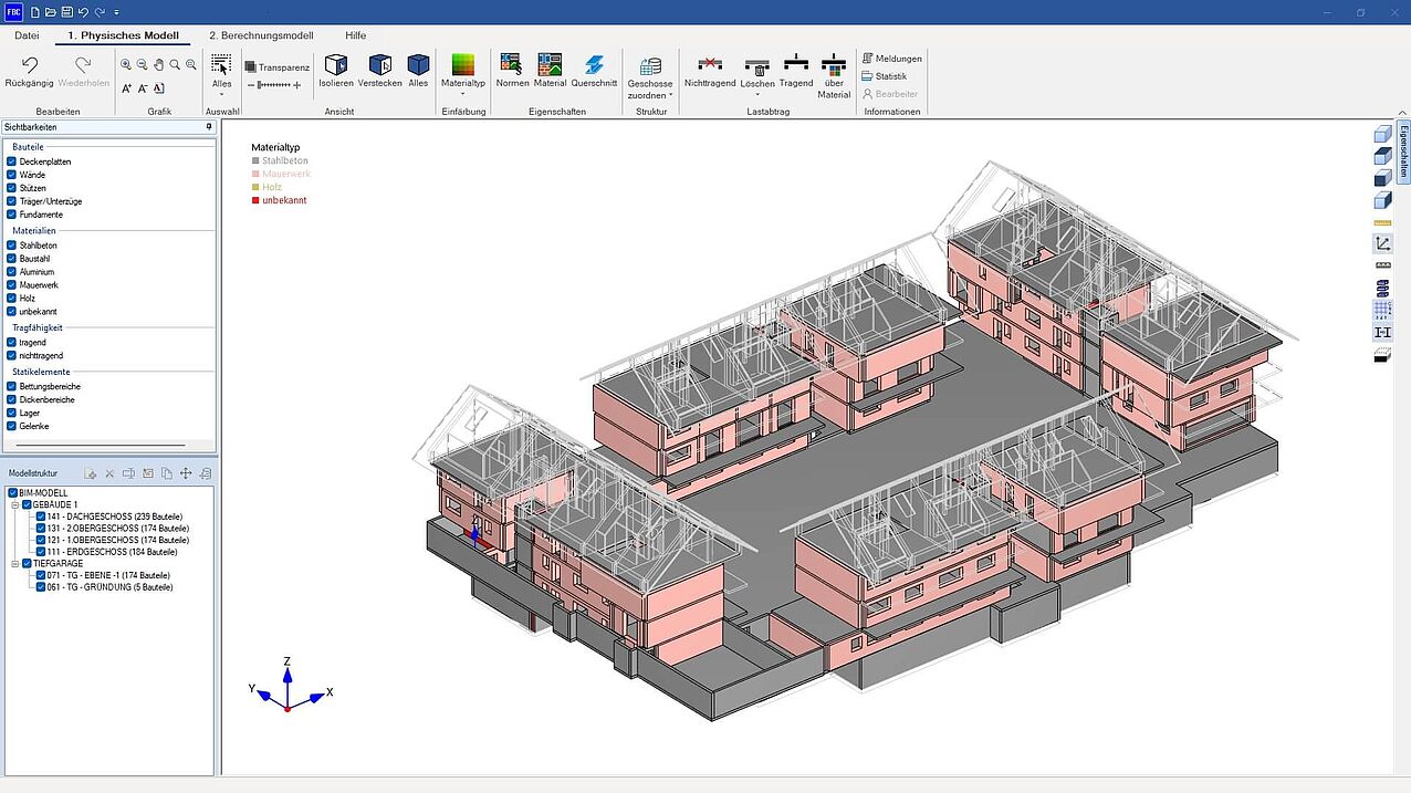
Based on the design created by the architectural firm Guggenbichler + Wagenstaller using Archicad, the draughtsmen at concon created their own structural engineering model in the CAD software ALLPLAN. “We make a point of creating a model early on, at the end of design development (HOAI service phase 3), so that we can continuously modify it to suit our work requirements during the planning process in service phases 4 and 5. On the one hand, the model serves as a basis for our draftsmen and building services engineers for formwork and reinforcement planning, the development of sound and fire protection plans, and energy-related support for the project in line with the specifications, including the associated thermal insulation certificates. On the other hand, our structural engineers also use the model to create a verifiable structural analysis,” explains Florian Lindner, managing partner at concon. When creating the model, care is therefore taken to correctly classify the load-bearing and non-load-bearing components and to assign the appropriate material and class to the components.
Efficient idealization of the structural model
After draftsmen and engineers had remodeled the architects' design while considering the structural engineering requirements, the model was transferred to the FRILO structural analysis software in the form of an IFC file. FRILO's BIM-Connector® not only acted as a link between the CAD and structural analysis software but also automatically generated the analytical model for structural analysis. By switching from the physical model to the analysis model, Dominik Dell, structural engineer at concon, reduced the model to its load-bearing components. “Because the materials and component classes had been correctly stored in ALLPLAN beforehand, I was able to quickly and accurately remove insulation, drywall, and other elements that are irrelevant to my structural analysis,” he says, adding: “The BIM-Connector® is extremely helpful when it comes to reducing a model to its structural elements in order to automatically derive an analysis model.” In order to ensure a clean, vertical load transfer, the structural engineer aligned the axes of the superimposed components and divided the walls into wall strips.
Rapid calculation of vertical loads
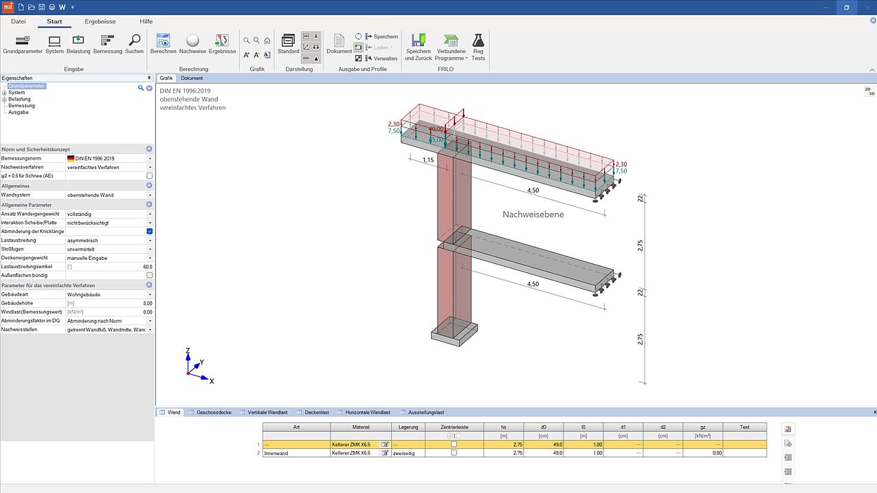
The analysis model idealized in the BIM-Connector® was then transferred within the FRILO environment to the GEO building model, where Lindner and Dell determined the vertical loads on the basis of the stiffness of the floor levels, floor by floor, from top to bottom. An FE calculation is performed in the background for each floor level. The support forces at the base of the load-bearing components are distributed evenly over the length of the component and transferred to the floor below until no further floor is found and a foundation is automatically generated. The geometries predefined in GEO and the calculated loads were then transferred to the FRILO programs for component design.
Component design with FRILO
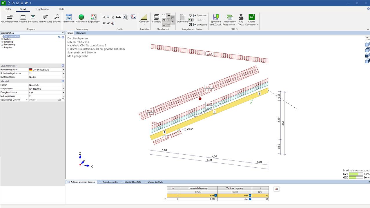
The individual and strip foundations on which the underground car park is built were designed using the FRILO programs FD+ and FDS+. The base resistance MR,d,max was limited to 550kN/m² and 500kN/m² respectively. The floor slab (concrete grade C25/30) and all reinforced concrete floor slabs were calculated using the finite element method with the PLT slab program. B6+ helped to provide the punching shear verifications. Lindner and Dell used the continuous beam DLT for the static calculation of the joists and wall beams. MWX+ and MWP+ were used for the verification of the exterior walls and masonry pillars. EDB+ was used to determine the additional earth pressures acting on the exterior walls in contact with the ground. For all reinforced concrete columns and the interior walls made of reinforced concrete, limit load capacity verifications were performed using the B5, using 1-meter strip. The rafters (softwood C24) of the roof structure were verified using DSP+. For the foot purlins (softwood C24) and the center purlins (glued laminated timber GL24c), the structural calculations were performed in accordance with DIN EN 1995-1-1/NA:2013-08 in the multi-span beam wood HTM+. “Ultimately, we used FRILO’s standard toolkit for the structural analysis of a project of this type,” summarizes Lindner.
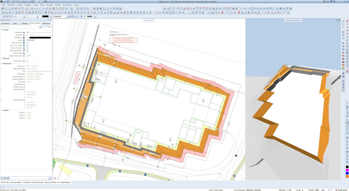
Execution planning with ALLPLAN
The civil engineers at concon continuously incorporated the analysis results into the structural design model in order to then prepare the position plans using ALLPLAN. The results from the structural design were adopted by the architectural firm. Once the position plans had been created, the architectural draftsmen at concon began working in ALLPLAN to draw the formwork and reinforcement plans for the required components. The reinforcement was laid directly in the ALLPLAN model, which enabled immediate collision checking. “Our engineering office has always placed great importance on the creation of 3D building models in ALLPLAN, because this allows us to derive the views for formwork and reinforcement planning from a single, continuously updated model. Changes to the model are immediately reflected in the views,” explains Karin Krüger, architectural draftswoman for building and civil engineering at concon. ALLPLAN is used daily at concon “…because a 3D model created and continuously adapted in ALLPLAN helps us to minimize errors and ensure consistent quality standards across the office's structural engineering, fire protection, and sound insulation departments,” summarizes Krüger.
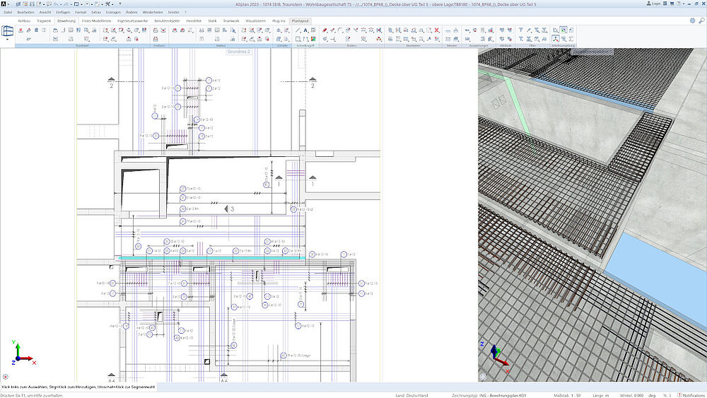 © concon; The view of the reinforcement inserted with ALLPLAN in a ceiling.
 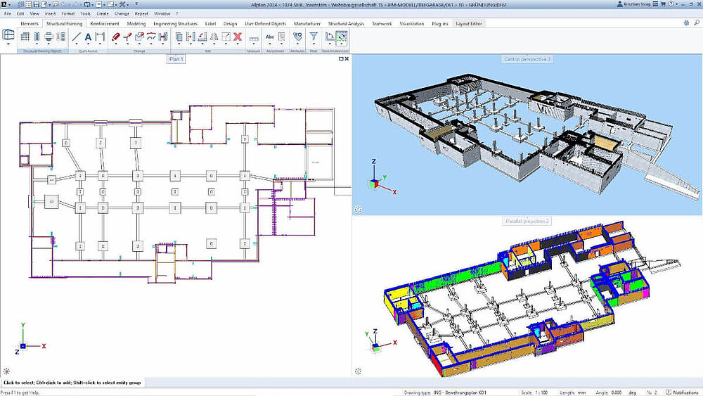 © concon; The engineering firm concon laid the necessary reinforcement in the 3D model in ALLPLAN.