Allplan Bridge 2024

ACCELERATE
DESIGN TO BUILD

Free Trial
Product presentation

Features Allplan Bridge 2024

More productive, powerful and automated bridge design workflows

The new Allplan Bridge 2024 version accelerates parametric bridge design to an all-new level. Never before have you been able to complete tasks so quickly using powerful and automated modeling and detailing tools, extended structural analysis capabilities, and streamlined digital design workflows. Giving bridge engineers the opportunity to optimize their designs, deliver projects earlier, maximize value for their clients and build better bridges.

Be faster with Allplan Bridge 2024:

  • Thanks to increased productivity
  • Through extended structural analysis
  • With superior design quality

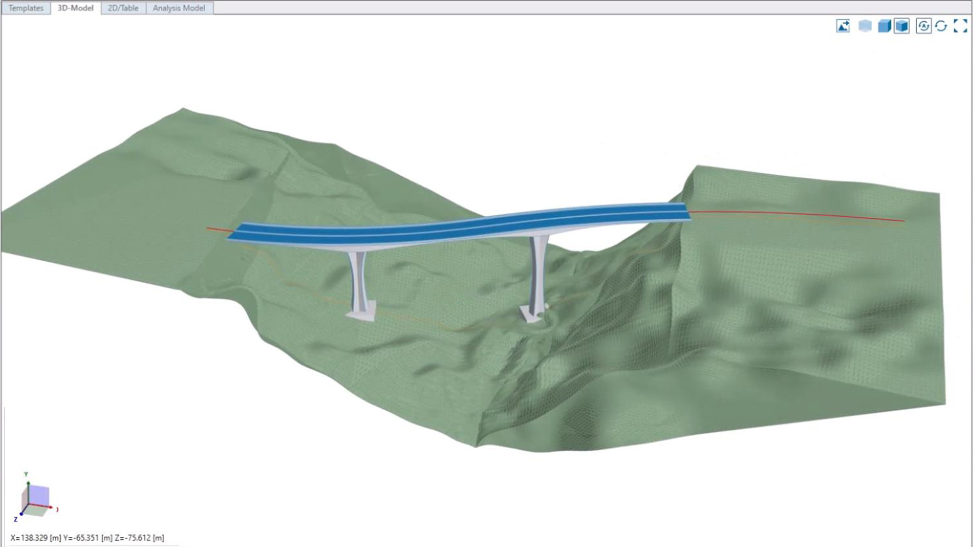
Terrain visualization with parametric referencing

Streamlined design processes

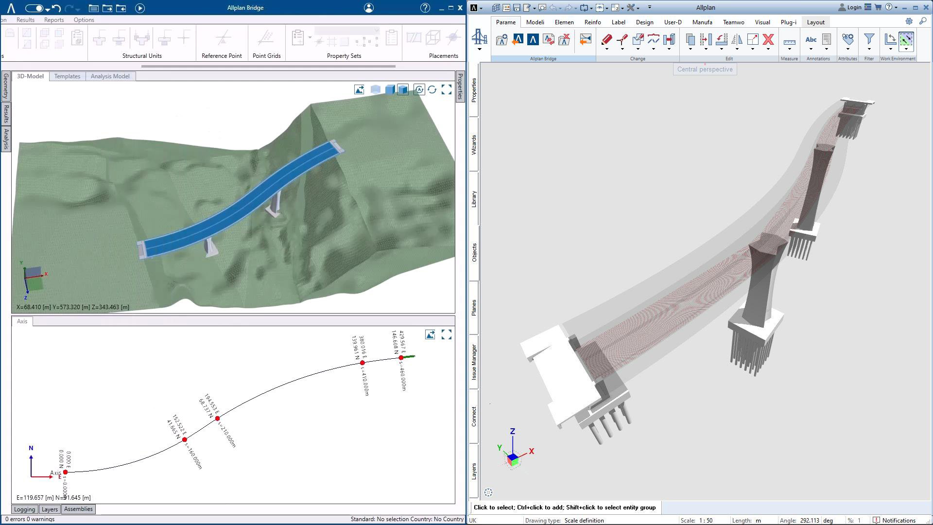
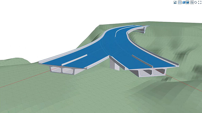
The primary aspects that require strong attention when positioning a new bridge into an environment are the bridge functionality, safety and aesthetic appeal. In the design process many factors such as the local topography, water, soil composition, and the presence of natural and man-made hurdles need to be investigated. With terrain visualization directly in Allplan Bridge, the design process is now significantly more streamlined.

Not only for visualization purposes, but the terrain can also be used for modeling and checking clearances. For example, it is possible to reference the substructure, like a pier or pile, relative to the terrain using a terrain axis, which is automatically generated. This is not only convenient for modeling, but also when changes are applied - because the complete definition is parametric, when a change is applied, e.g., girder height, the pier height is automatically adjusted.


Import of super-elevation data via Allplan Cloud

More efficient design work

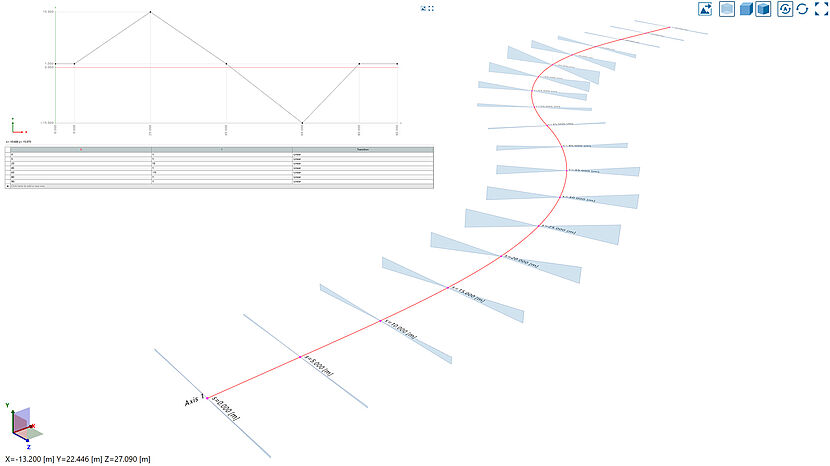
The axis and the pavement geometry (section) are normally defined by the road engineer. The axis is defined by the plan and elevation geometry and the pavement is defined by one or several cross-slopes and corresponding widths which vary along the axis. All of this needs to be considered while modeling bridges. In order to minimize, if not omit, re-entering of this data, in Allplan Bridge it is now possible not only to import the geometry of the axis, but also the corresponding definition(s) of cross-slope.

Parametric Reinforcement Connection

Faster and more productive detailing

It is always a challenge to produce BIM reinforcement models and detailing drawings to the required quality standards within a reasonable timeframe whilst maintaining a satisfactory margin. Ensuring quality without hurting productivity and profitability is a constant challenge for engineering and detailing companies for every reinforcement project, regardless of the project type and location. ALLPLAN understands this, which is why Allplan has been specifically developed to overcome common rebar detailing issues.

With Allplan Bridge 2024 the next big step is taken. Two parametric technologies have been combined to provide a parametric design-to-build solution, namely the parametric modeling solution of Allplan Bridge and PythonParts in Allplan. In Allplan Bridge reinforcement sets are defined, primarily for reinforcement design and code checking, and these reinforcement sets are now parametrically connected with the PythonPart technology in Allplan. Not only is the geometry of the longitudinal, shear and torsion reinforcement transferred to Allplan but also all other information, like position of bars, number of bars and bar diameters. As a result, a fully parametric design-to-build workflow is possible, which results in faster and less error-prone work, and enables higher quality, productivity and profitability at the same time.


Free Parametric modeling 2.0

Powerful, flexible and time saving modeling

In Allplan Bridge there are three main modeling methods. The initial approach uses the 3D form of the axis for extrusion of a cross-section to create an exact geometry. However, in bridge structures, as there are often elements which do not follow the axis, such as precast girders, a further modeling approach especially tailored for these bridge elements was required and implemented in one of the previous versions.

In version 2023 a third modeling approach was released - Free Parametric modeling. With version 2024 this modeling approach is significantly enhanced and is becoming even more powerful, because it is extended in such a way that any modeling element in Allplan Bridge, such as a girder, pier, link girder, or deck, can be extracted into a 3D body and used freely. The model remains fully parametric, as the extracted body seamlessly adapts to any change. Furthermore, the extracted body can be utilized for Boolean operations, employed as a template, and freely moved within the modeling space.

A further improvement, regarding free parametric modeling, is the usage of more prism elements in one prism template and combining them using Boolean operations. This enables the creation of more intricate objects such as abutments as templates which can be easily placed and positioned multiple times in one bridge model and can be easily exported and used in other projects.

Body Containers is another powerful improvement. It is a novel type of object that operates within its own local coordinate system. Within this system, users can position 3D docking points with varying relationships to the container origin which allow for placing 3D bodies. Body Containers have the capability to accommodate multiple body groups, further enhancing the modeling workflow and facilitating the inclusion of even more complex objects.

Automatically derived calculation actions

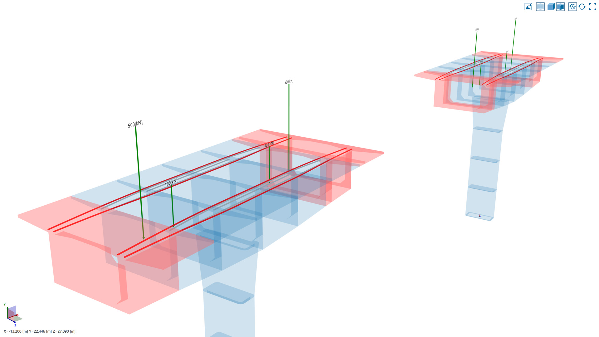
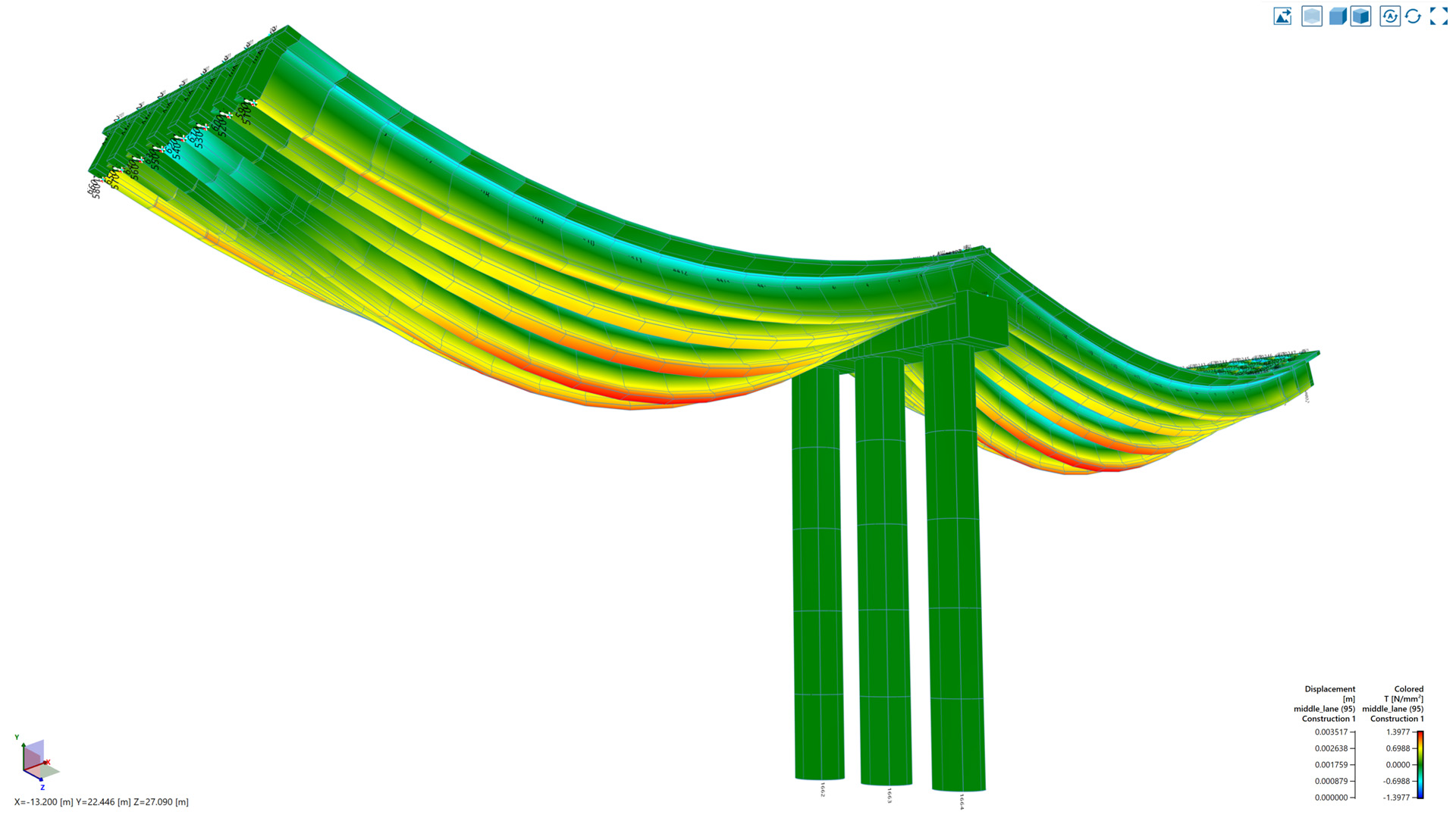
Specialized loads for cantilever construction method

The balanced cantilever construction method is an often-used technique for building bridges. Starting at a pier, individual segments (prefabricated or cast in situ) are assembled step by step on either side in a symmetric or unsymmetrical sequence. Form travelers are used to establish the segments and are moved forward from stage to stage. During this cycle, various types of loads are acting on the bridge which have to be considered at their proper position and point of time in order to reflect the correct structural and time-dependent behavior.

The new balanced cantilever task in Allplan Bridge 2024 only requires an object-oriented input of the geometric data of the form traveler as well as the time schedule of the particular construction steps. While all this data is provided in just one clearly arranged input window, it will result in numerous calculation actions carried out automatically, such as applying/moving the traveler, pouring/assembling the segment, applying the self-weight, pre-stressing the tendons and properly considering creep and shrinkage during all the changing load applications.


Further national annexes to EN

Easily design to key national standards

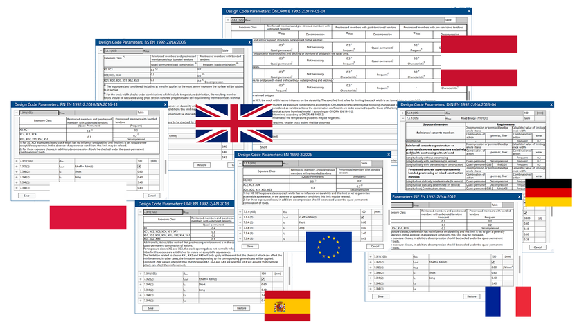
Development of the latest version of Allplan Bridge in a code-based design module has been focused on the introduction of three new national annexes and their specifics. The implementation of the latest valid version of national annexes is now available for Germany (DIN EN), France (NF EN), Spain (UNE EN), the UK (BS EN), Austria (ÖNORM EN), and Poland (PN EN). All limit states are now covered by annex-specific limit values or methods and are also referenced in the reports.


Allplan Bridge Reporting Tool

Revolutionize the reporting process

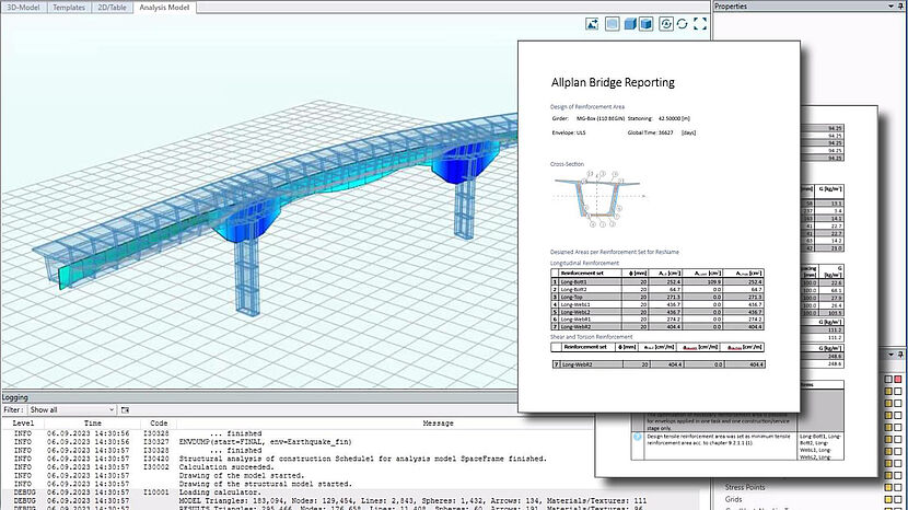
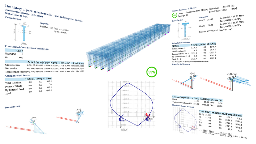
Allplan Bridge 2024 connects two worlds into one and with this revolutionizes the reporting process by offering a range of powerful features that enhance efficiency, accuracy, and visual impact. Bridge design and analysis data in the form of tables, images, 2D and 3D diagrams, and much more, can be easily linked and positioned directly into MS Word documents. This eliminates the need for manual data entry and updates, saving time and reducing the risk of errors.

The drag and drop system ensures the seamless integration of data into user-defined reports. The established link ensures that all data is up to date. Any changes made in an Allplan Bridge project, such as modifications to design elements, calculations, diagrams, images, tables, and design snippets, are automatically reflected in the structural report. This real-time update feature eliminates the need for manual updates, ensuring accuracy and saving valuable time. Furthermore, a post database is provided allowing users to store and filter relevant results. This allows for quick access and analysis of important data. It is possible to create custom queries, apply filters, and sort through extensive data to generate tailored tables.

Key benefits of the Reporting Tool:

  • MS Word AddIn - using the tool everyone is used to work with
  • Dynamic Data-Link (Parametric)
  • Real-Time Update
  • Customizable tables using post-database
  • Comprehensive support for Visuals

Summary Report

Automatic summary of the design and code checking

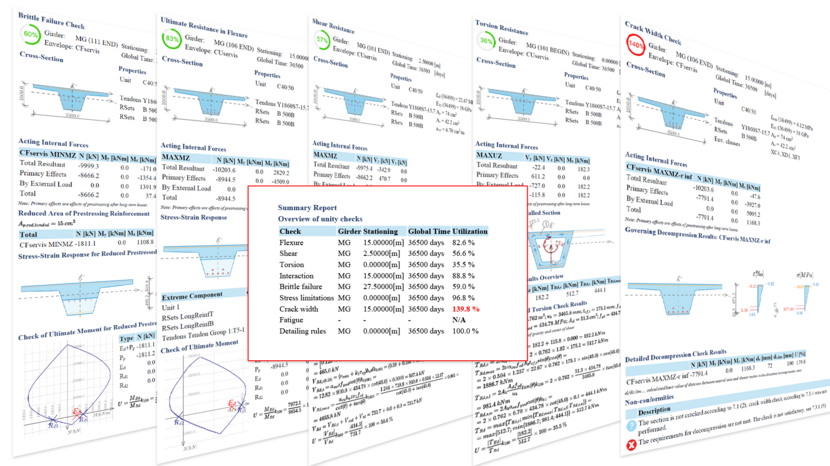
The extensive output capabilities of reinforcement design and code checking procedures are extended by a new type. The so-called “Summary Report” gives an overview of the governing results of the code design and checks. Allplan Bridge 2024 runs the code checks with the appropriate result names. For each section, the results are saved and subsequently, the governing results are filtered in a loop for all result names and all sections. Then the governing sections and results and sorted, extremes are found, overview tables are generated, and the detailed results are nested into the summary report.

Structural analysis of Composite bridges

Technical preview: New analysis capabilities for composite bridges

Composite structures are advanced engineering solutions that combine different types of materials, for bridges typically steel girders and concrete deck, as well as the same type of material assembled at a different time, such as precast concrete girders with cast in situ reinforced concrete deck. Furthermore, this solution can also be used for calculation of bridge rehabilitation.

The global structural analysis capabilities in Allplan Bridge were enhanced to correctly consider the behavior of composite structures. For example, the construction sequence calculation considers not only newly added structural components, but also already activated cross-sectional components. This results in a fundamental change in stiffness. For composite sections it is based on the calculation of transformed section values using typical ideal material for the composite unit. Furthermore, the solution correctly considers the difference in creep and shrinkage behavior of different partial members, resulting in overtime intrinsic forces (stresses) in the partial members. Besides all permanent loads, the solution allows users to consider also all variable loads, like traffic or earthquake. For these loads, the composite members are loaded and calculated forces are automatically split and correspondingly assigned to the partial members, where they are available for design functions.


New code-based design features

Extending Design and Checking procedures for composite sections

In addition to the global analysis of composite structures also the design module was enhanced with code assessment of composite concrete-to-concrete cross-sections. The cross-section may consist of a post-tensioned structural unit and a concrete slab cast at a later stage of construction. Any stress state of the cross-section can be analyzed during the construction and service stages. Above that the checks of the ultimate and serviceability states can be carried out in accordance with the applicable standards. The assessment also includes an evaluation of the stresses at the interface between the old and new concrete and the check of the reinforcement capacity in the joint.


Further new features and improvements

A number of further new features and improvements are available. For example, accompanying polygonal axis allows modeling of longitudinal linear infrastructure objects, like noise-barriers or Jersey-like concrete barriers. There have been several new reporting and output functionalities additions, such as improving the output of the axis geometry, or stakeout report using the reference points defined in a cross-section which is assigned to a structural member.

Referencing an external boundary to the intersection of two parametric construction lines will improve the modeling process and the load visualization in the construction sequence definition improves the structural analysis workflow and represent yet another product improvements for the version 2024.

Technical support from bridge experts

ALLPLAN’s bridge design experts have over 30 years’ experience supporting engineers worldwide. ALLPLAN’s clients can benefit from our technical experts providing comprehensive consultancy, training and support.

ALLPLAN Software Engineering GmbH
Competence Center Allplan Infrastructure

Kaiserfeldgasse 1, 8010 Graz, Austria
Telephone: +43 316 269786

Allplan 2024

A NEW ERA IN PARAMETRIC BRIDGE MODELING.
Shaping Bridges in a better way with Allplan

Try Allplan for bridge engineering for free

  • Free parametric modeling - flexible and time saving
  • Easily design to key national standards (German, Spanish and French)
  • Avoid repetitive tasks with powerful templating and improved project collaboration
  • Smoother analytical interoperability
  • Improved collaboration with Allplan Engineeringsoftware

Test the full version of Allplan for Bridge Engineering 2024 for 14 days free of charge and with no obligation. Simply download the software and experience all the advantages for yourself.

Download Now


Allplan product presentation

Register now to set up a call