Features ALLPLAN Bridge 2023
Shaping Bridges in a better way with ALLPLAN Bridge 2023
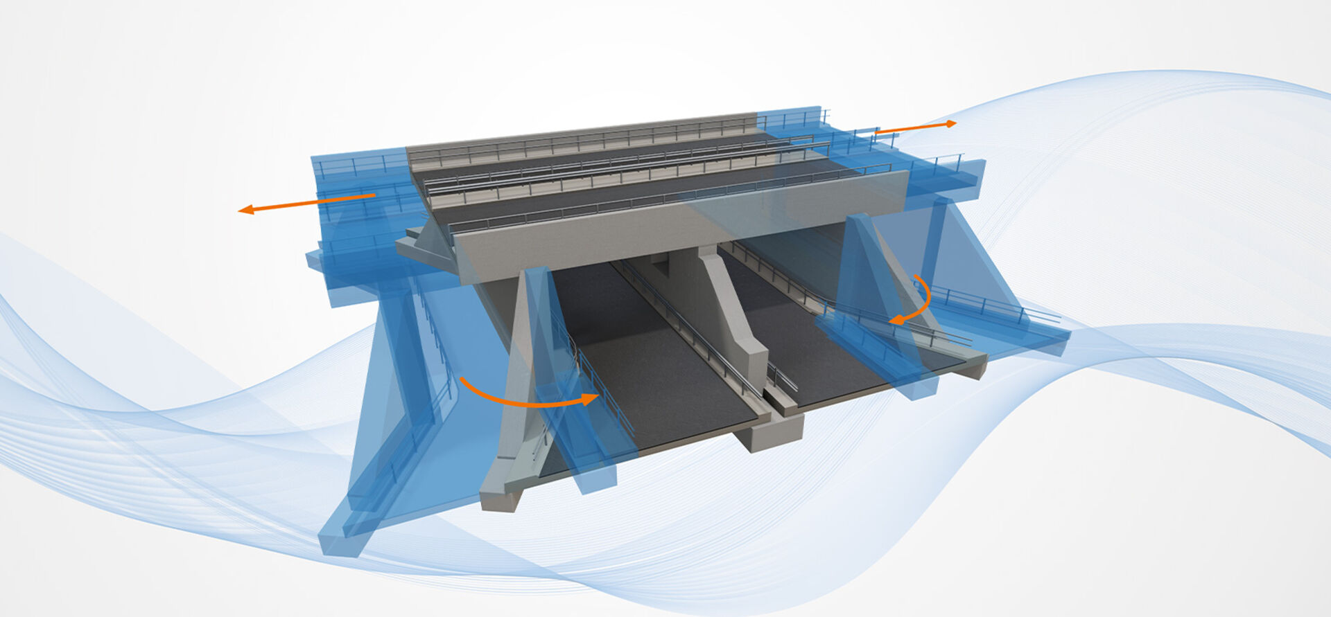
ALLPLAN Bridge introduces a new modeling method – free parametric modeling. It enables the parametric modeling of an entire bridge or its sub elements freely in 3D space. For example, smaller integral bridges, underpasses, etc., can be parametrically modeled efficiently. Furthermore, the implementation of changes and also the generation of templates for complete bridges is available interactively and without any scripts. Additionally, as this is a more general parametric modeling technique, it can also be used for modeling other infrastructure facilities.
Further important product enhancements are the extensions of the national annexes. Reinforcement design and code checking procedures are now available for the German, Spanish and French annex. The latest version also includes numerous enhancements, such as improved collaboration with ALLPLAN Engineering, 2D Diagrams, Nonlinear Temperature Load, External Tendons, Fatigue Check, and many more.
New Verification Example
Fully demonstrate Eurocode compliance
The new verification example demonstrates and verifies the calculation methods used in ALLPLAN Bridge for reinforcement design and code-checking. For this a simply supported single-span pedestrian bridge designed as a prestressed concrete girder with a single solid T-shaped section with haunches is used. This example will help users to fully understand the inputs and the results provided.
Free Parametric Modeling
Flexible, time saving parametric modeling
In ALLPLAN Bridge there are two main modeling methods. The initial approach uses the 3D form of the axis for extrusion of a cross-section to create an exact geometry. However, in bridge structures, as there are often elements which do not follow the axis - such as precast girders, a further modeling approach especially tailored for these bridge elements was required and implemented in the previous version.
With the version 2023 a new modeling method is now available - it enables the parametric modeling of an entire bridge or its sub elements freely in 3D space using volumetric primitives and Boolean operations. In the first release of this new technology in ALLPLAN Bridge for volumetric primitives, advanced prisms are implemented – such that the basic shape of a prism is defined using the well-known cross-section definition. Through this total freedom is given for modeling of simple 3D shapes, like cubes and cuboids, cylinders, parallelepipeds and more complex shapes such as abutment walls and many more. Furthermore, prisms can be modeled directly or can be prepared as templates. In the final step, prisms are unified using 3D Boolean operations.
The prisms are parametrically linked between each other or relative to other bridge elements, such as a main girder. Not only through their geometrical reference but also all the modifications (like move or rotate) are stored and can be edited at any time.
All of this results in a fully parametric model that can be easily adapted and with that the complete project or parts of it can be saved as templates and reused at any time.
This is a more generic modeling approach and therefore can be used in a much broader sense.
EN National Annexes for Germany, France and Spain
Easily design to key national standards
Development of the latest version of ALLPLAN Bridge in a code-based design module has been focused on the introduction of the first 3 national annexes and their specifics. The implementation of the latest valid version of national annexes is now available for Germany (DIN EN), France (NF EN), and Spain (UNE EN). All limit states are now covered by annex-specific limit values or methods and are also referenced in the reports.
Fatigue check
Design durable bridges
Fatigue check, based on the damage accumulation method, was added to the list of code checking features for Eurocode users. This feature provides the possibility to prove the safety of the engineer´s design for fatigue to the end of the design working life. The traffic loads can be input at different times to enable the change of traffic intensity or type. On each date, the “master task” is created that can contain multiple subtasks, each representing one vehicle type acting from this time on, a corresponding combination of internal forces, and a number of cycles per annum.
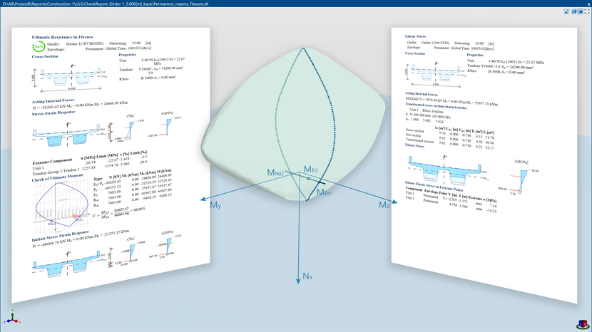
Reports for reinforcement design
Minimize errors with a transparent design overview
The new version extends the deliverables of reports by a new type. The so-called overall information report provides the information about standards, national annexes, selected industry codes, and their versions. All code-dependent values are plotted as a table, with the user´s changes highlighted, so the calculation with correct values can be verified. In the last part of this report the material stress-strain relationships, values, and assumptions are included per material and limit states. This report type is created automatically when the construction schedule is performed with at least one code-based design module task.
Templating and enhanced Project collaboration
Avoid repetitive tasks with powerful Templating and data exchange
The best way to improve your productivity is to automate repetitive tasks. Instead of repetitively modeling similar objects, one standard object could be created and used multiple times. This should not be limited to modeling only but rather applicable to the entire design process. All of this is possible by combining templating with parametric modeling. This is because a set of variables that influence the parametric model can be linked with the template’s input for an automated workflow. In addition to this, ALLPLAN Bridge provides the means to easily reuse a complete project. With the new function to extract, save and import partial parts of a project, any data can be reused effortlessly. With this, redundant data input is significantly minimized, if not avoided. Thus, projects can be delivered even more efficiently.
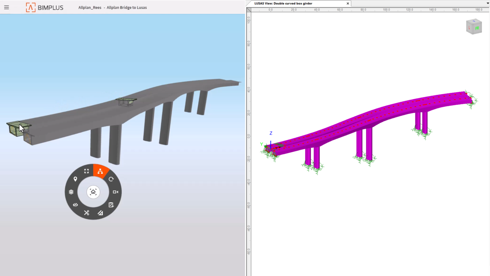
Improved collaboration with ALLPLAN Engineering
Powerful data interaction for construction deliverables
When it comes to the organization of data every user likes to organize their data in such a way that it is most sensible – in ALLPLAN Bridge this is accomplished using the “Custom tree.” In ALLPLAN this is achieved using the drawing files. For visualizations, reinforcement modeling, detailing and drawing production the model from ALLPLAN Bridge is not only transferred but also linked. In the new version a further “link” is established between the “custom-tree” in ALLPLAN Bridge and the “drawing files” in ALLPLAN, empowering controlled data transfer and improving the update process.
Dependency-tree based solver
Optimized performance for smoother change management
The new modeling method, free parametric modeling, follows the main product philosophy, namely that all the modeling elements are connected parametrically. This is true not only for the new prism elements but also for all the Boolean operations that are possible. To allow for smooth management of changes, also for larger and more complex structures, in ALLPLAN Bridge the complete geometry calculation now uses a new and more advanced calculation procedure – “dependency-tree based solver”. This algorithm generates a tree of dependencies between individual objects such that only the part of the model which is affected by the implemented change is recalculated.
2D diagrams
Clearly communicate structural behavior
In ALLPLAN Bridge it is possible to display the results of structural analysis, and reinforcement design in the form of tables and 3D Diagrams. In the new version of ALLPLAN Bridge the results can be visualized also in form of 2D diagrams which provide an easy and concise presentation of results and clear communication of structural behavior.
Link-to-link
Boosting modeling practicality of Link girders
Link Girders are 3D linear elements positioned between two 3D points. The 3D points are created by reference points defined in cross-sections used in girders, piers, bodies, etc. An arbitrary cross-section can be assigned, and any variation can be modeled. This allows users to use Link girders in many different ways, for precast girders, steel girders, overhang supports, different bracings and many more. In the new version it is also possible to connect link girders between each other.
Nonlinear temperature load
Consider environment effects correctly
Once the bridge structure is put into service it is exposed to different temperature variations daily and seasonally. This affects not only movements of the structure, for the design of bearings, but also the stresses within. The load is often split into two components, the uniformly varying component and the linearly or nonlinearly distributed component. With the new version of ALLPLAN Bridge, it is possible to also apply the nonlinear temperature load distribution. The load can be applied in any direction, and with this the most common directions are covered – vertical and transversal – for both heating and cooling.
The load is correctly considered when performing the global analysis and the detailed design. It affects almost every part of design and check procedures, as the distribution of temperature strains/stresses arising in the form of residual stresses is not linear across the cross-section. This fact, and the possible change of temperature and bending moments in both directions are highlighted by new 3D pictures plotting this behavior so the general 3D shape of strain/stress distribution is more understandable to the user.
External tendons
One solution for both, modeling and analysis
Unbonded tendons (internal and external) are a new feature of ALLPLAN Bridge structural analysis that has also an influence on the code-based design module. The calculations follow up the linear elastic analysis and therefore a recommended solution is used. Both AASHTO and Eurocode standards allow for using the method of increased tendon stress at the ultimate (strength) limit state. The combination of bonded and unbonded tendons is possible in the project and the effect of increased stress is performed only for unbonded tendons.
Stiffness reduction in modal analysis
One analytical model for static and dynamic analysis
ALLPLAN Bridge uses the multi-mode Response Spectrum Method for evaluating the effects of seismic loading. The solution consists of 2 separate tasks in the calculation procedure, firstly the determination of the relevant natural modes of the structural system and secondly the evaluation of the response spectrum prescribed in the design code. With the new version of ALLPLAN Bridge it is possible to reduce the torsional stiffness in the form of a user defined factor for selected bridge elements. The reduced stiffness is used only for the modal analysis enabling only one calculational model, for static and dynamic calculations.