Special bridges often bring some of the most demanding detailing challenges in infrastructure design. Complex geometry, prestressing systems, stay cable components, and dense reinforcement all need to work together accurately before construction begins. For the Banas River Extradosed Bridge in Rajasthan, SPECTRUM Techno Consultants is using ALLPLAN and ALLPLAN Civil to bring these elements together in a coordinated 3D workflow.
In summary: > SPECTRUM is using ALLPLAN to deliver the detailed design of the Banas River Extradosed Bridge in Rajasthan. > Parametric modeling in ALLPLAN Civil helps manage the bridge’s complex, variable box girder geometry. > Prestressing, stay cable components, and reinforcement are brought together within a coordinated 3D workflow. > Detailed reinforcement modeling helps identify potential clashes in congested areas before they reach the construction site. > SPECTRUM plans to extend its ALLPLAN workflows into automated deliverables, Digital Twins, and further design automation. |
SPECTRUM has extensive experience in complex bridge design, including eight operational cable-supported bridges with spans of up to 180 meters and several ongoing projects with spans reaching 300 meters. The Banas River project provides an opportunity to apply that experience within a developing BIM workflow for detailed bridge design and reinforcement modeling. Here’s how they overcame the unique challenges of this particular bridge.
A Bridge with Challenging Geometry
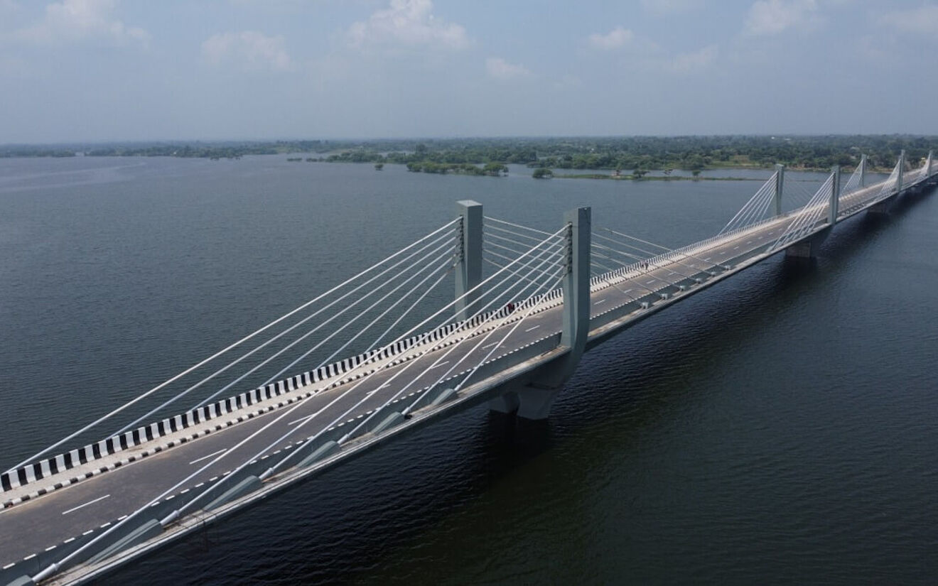
Located downstream of the Bisalpur Dam across the Banas River in Rajasthan, India, the bridge is owned by the Public Works Department of Rajasthan and is being delivered in EPC mode by the DRAIPL-ALTIS joint venture. SPECTRUM is responsible for the detailed design of the extradosed bridge.
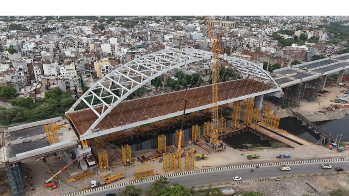
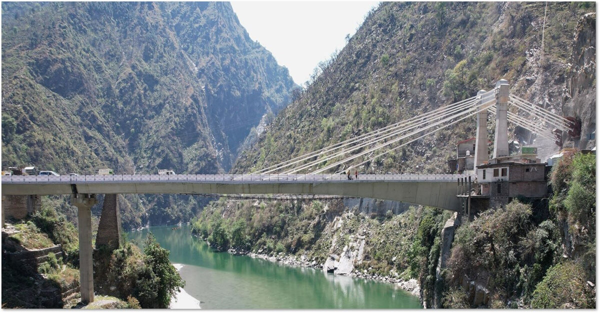
The extradosed portion has a span arrangement of 72 + 144 + 72 meters and a 15-meter-wide deck. Its cast-in-place box girder is constructed using the balanced cantilever method, with the superstructure depth varying from 5 meters at the supports to 3 meters at midspan and the expansion joints. The pylons rise 15 meters above the deck and feature a distinctive geometry that adds further complexity to the detailing process.
These characteristics create a demanding coordination challenge. The concrete geometry must accommodate prestressing systems, stay cable components, reinforcement, and other local details within areas where space is limited and structural demands are high. Resolving these relationships clearly in three dimensions is therefore an important part of preparing the design for construction.
Building the Bridge Parametrically
For the box girder superstructure, SPECTRUM used the parametric capabilities of ALLPLAN Civil. The model was set up to account for changes in girder depth, web thickness, soffit slab thickness, and haunch geometry along the length of the bridge.
Rather than manually recreating every changing section, these dimensions can be controlled through parameters assigned along the bridge axis. This gives the design team a structured way to represent the variable geometry while maintaining consistency throughout the model.
Other bridge components were modeled in ALLPLAN, including the foundations, pylons, expansion-joint piers and segments, stay cables, cable anchors, and prestressing blisters. These were then combined with the parametric superstructure model to create the complete bridge geometry to LOD 300. For SPECTRUM, this combined approach provided a practical way to use the strengths of both ALLPLAN Civil and ALLPLAN while developing its wider BIM delivery procedures.
Bringing Prestressing into the 3D Model
Existing design information was also incorporated into the BIM workflow. Although prestressing cables can be defined parametrically in ALLPLAN Civil, SPECTRUM already had the cable geometry available from another analysis application. The team therefore extracted this information as 3D polylines and used it to model the internal prestressing directly in ALLPLAN.
This included the top and bottom cables within the box girder, as well as the prestressing blisters used to terminate soffit cables. Stay cable anchors and saddles were also incorporated into the model, with specialist information from the stay cable vendor added as it became available. By bringing these components together within the same 3D environment, the design team was able to better understand how the structural systems interacted before moving into detailed reinforcement design.
Solving the Reinforcement Detailing Challenge
Reinforcement detailing is where SPECTRUM’s 3D approach became particularly valuable. At the foundation level, the team modeled the reinforcement within the piles and pile cap, taking into account potential clashes between the pile, pile cap, and pier reinforcement. The reinforcement around the lower pylon and pier head introduced further complexity as the different structural elements intersect here.
One of the most challenging areas was the stay cable saddle within the upper pylon. This highly stressed location required intricate reinforcement around the saddle components. According to SPECTRUM, visualizing this arrangement in 2D was difficult. However, using 3D modeling allowed individual bar shapes to be positioned more precisely and checked against surrounding components.
The same principle applies to prestressing cable blisters within the box girder. These areas can create difficult reinforcement conditions on site, particularly where reinforcement and prestressing systems occupy the same congested space. By modeling the reinforcement in advance, SPECTRUM was able to pre-check potential clashes and prepare the bar arrangement accordingly.
For the construction team, this provided a much clearer representation of how the reinforcement should be placed. Using the model this way also reduced the need for experimentation on site by resolving more of these issues during detailing.
Turning Complex Design into Buildable Information
The Banas River Extradosed Bridge shows how detailed 3D modeling can help bridge the gap between complex structural design and practical construction information. By combining parametric bridge modeling in ALLPLAN Civil with detailed geometry and reinforcement modeling in ALLPLAN, SPECTRUM brought together some of the project's most challenging components within one coordinated workflow.
For complex bridge structures, the ability to understand interactions before they reach site can be particularly valuable. It supports clearer detailing, better coordination, and a more direct path from design intent to buildable information – which is exactly where BIM can make the greatest difference.
For SPECTRUM, this project is just one step in a wider BIM journey. Building on the workflows developed for the Banas River Bridge, the company plans to use ALLPLAN for automated construction deliverables and quantity takeoffs, while progressing towards greater design automation, LOD 500 as-built models, and Digital Twin applications for lifecycle asset management.