
ALLPLAN Civil
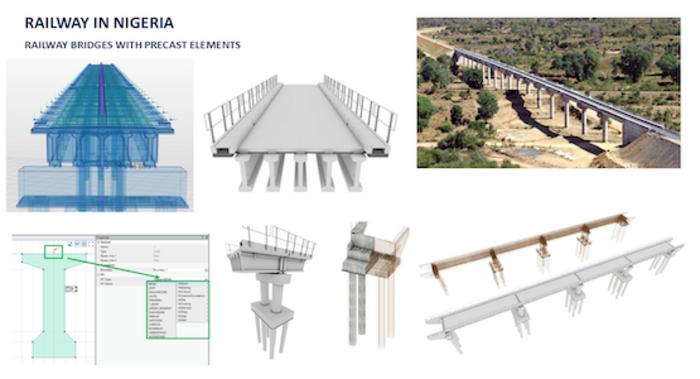
Precast girder bridges workflow
The geometry of precast girders is governed by the geometry of the substructure and their position along the axis. Thus, a further modeling approach is available in ALLPLAN Civil that enables users to create an exact geometry of precast girder bridges easily and quickly.
Watch now
TAILORED AND AUTOMATED WORKFLOW FOR PRECAST GIRDER BRIDGES
With up to 70% automation, this innovative and comprehensive design-to-build workflow significantly reduces workload and delivers substantial time savings. It incorporates integrated structural analysis capabilities tailored to the entire lifecycle of bridges and their precast components, along with advanced features for the precast industry such as dedicated parametric modeling and detailing as well as drawing production. The fabrication of precast and pretensioned girders involves several specialized processes. Of particular note is off-site construction, which allows for controlled concrete curing through heating, thereby significantly reducing production timelines. These unique methodologies require careful integration into both global and local structural analyses, capabilities that are now available in ALLPLAN and presented below.

1.1 CREATE AXES
Every bridge construction project starts with one or more axes – with ALLPLAN Civil, you can adopt the data from an existing design (e.g.: using LandXML data format) or define it manually. In both cases, the alignment is parametrically saved.

1.2 DEFINE A CROSS-SECTION
You can define any cross-section and determine the geometry with its dependencies and variables. These parametric cross-sections can be adapted at any time and can be saved as a template and reused. Furthermore, for certain standardized girder sections templates are available.

1.3 DESIGN A TEMPLATE
Any geometry of a pier, foundation and precast girder can be defined as a template. In the previous step defined cross-section(s) including constant and variable parameters are used for the design of the template. If the geometry is variable, tables or formulas can be assigned as usual. Furthermore, you can set which parts of the template should be fixed and which should adjust when using it in the 3D model.

1.4 BUILD A SUBSTRUCTURE
The substructure, with or without foundations, can be defined relative to one axis or relative to two axes – for example terrain axis at the bottom and road axis at the top. It can be defined directly or by usage of templates.

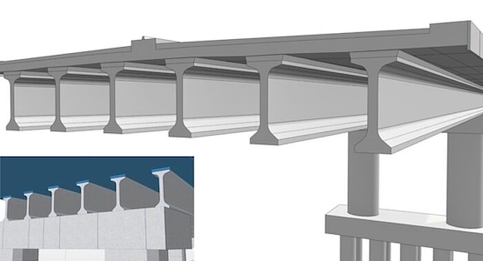
1.5 ASSEMBLE GIRDERS
Precast girders are, just like on the construction side, positioned on the substructure created in the previous step. Actually, they are positioned between 2 reference points (bearings). The exact position of reference points is set by the substructure geometry.

1.6 CONSTRUCT A PLATE
For generating the plate geometry, the main workflow of ALLPLAN Civil is used – extruding the geometry along the axis. Also, here any variations can be used and the cross-section, and with this also the 3D model can be equipped with all the details either by using boundaries or by placing python parts.

1.7 COMPOSE THE HAUNCH
In precast girder bridges the shape of the girders is governed by the geometry of the substructure, whereas on the other side, the geometry of the plate is governed by the axis. This is why the shape of the haunch has an arbitrary 3D geometry and varies along the girder. ALLPLAN Civil 3D Boolean operations are used to automatically fill the space between the girder and plate, using the shape of the haunch defined in the girder cross-section.

1.8 COMPLETe THE BRIDGE STRUCTURE
Once the main bridge elements are finished, further elements and details, like tendons, diaphragms, bearings and many more, can be generated. This can be done by modeling them or by placing parametric elements – python parts.
1.9 Automation
Automation is achieved through parametric templates, which come in two main forms:
1. Complete Bridge Models – These templates represent entire bridge structures, such as 2- or 3-span girder bridges, allowing key parameters like span length, bridge width, and the number of girders to be customized.
2. Modular Bridge Components – These templates cover individual bridge elements, including abutments, precast girders, piers, foundations, and decks, enabling a flexible, component-based approach to bridge modeling.
Both types of templates incorporate not only geometry and BIM data but also the analytical model and structural reinforcement details.
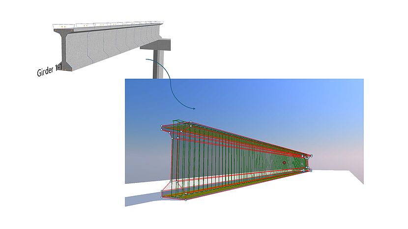
2.1 DERIVE STRUCTURAL ANALYSIS MODEL
Thanks to the breakthrough technology, ALLPLAN Civil semi-automatically generates the analysis model from the geometrical model. This greatly reduces the amount of work and the susceptibility to errors. Hereby the engineer retains full control by specifying structural parts and those ones which contribute as load only. One of the additional analysis-relevant definitions is the choice of generating a beam or a grillage model.

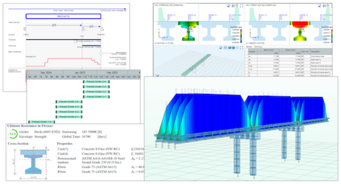
2.2 DEFINE CONSTRUCTION STAGES
Time as the 4th dimension is considered by easily specifying the construction process. The construction plan is divided into several phases and further into individual tasks, such as girder placement, stressing pre or post-tensioned tendons, etc. The related structural components are interactively assigned to these tasks.

2.3 DETERMINE PREFABRICATION PROCES
The prefabrication process simulates key stages in the casting bed, including strand stressing, concrete casting, force transfer, and the heating cycle. This enhances the global structural analysis, particularly by incorporating adopted time-dependent effects like creep and shrinkage, and accelerated steel relaxation, all tailored to the unique behavior of precast girders during fabrication.
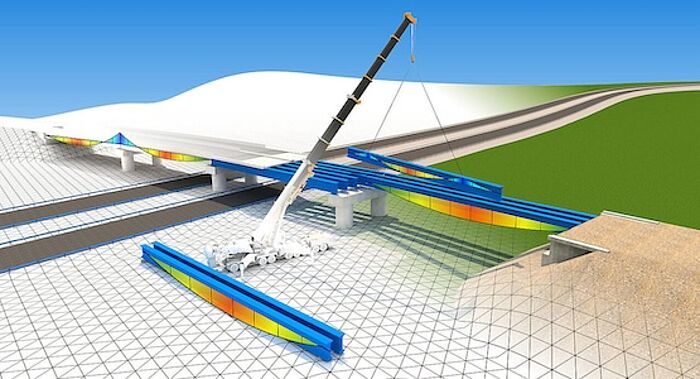
2.4 SIMULATE STORAGE AND TRANSPORTAION
After the fabrication process is complete and before the girder is placed in its final position, the girder undergoes multiple stages including lifting, storage, and transportation. All of this can be simulated in ALLPLAN and additionally enhances the global structural analysis and the design and sectional assessments of precast, pretensioned girders.

2.5 DEFINE ALL PERMANENT AND VARIABLE LOADS
Once the bridge is virtually constructed, the digital construction process continues with application of superimposed dead loads (e.g., sidewalk, pavement) auto-retrieved from the geometrical model. Users specify the timing of equipment installation, for applying the load to the structure. Additional loads like temperature, wind, or traffic are easily defined per standards. The generic approach for traffic loads allow to apply any moving load. Calculations identify the most unfavorable traffic effects, first calculating influence lines, then evaluating them with the load train and storing results in an envelope.

2.6 EARTHQUAKE LOAD
ALLPLAN Civil uses the multi-mode Response Spectrum Method for evaluating the effects of seismic loading. Mathematically, this solution is based on the excitation of the relevant natural modes and combining the different modal contributions. Internal force and displacement amplitudes related to the individual natural modes are superimposed using different methods, such as the Complete Quadratic Combination (CQC) to get the envelope of extreme values.

2.7 SUPERPOSITION & COMBINATIONS
The user-friendliness and usability of the superposition in ALLPLAN Civil is groundbreaking. The schematic definition of the superposition combines maximum flexibility and optimal overview. Same applies for the combinations, which are defined and visualized in a table form, giving the user an optimal overview of different combination types and load factors. Furthermore, it is possible to select several stress components in user-defined stress points and perform a stress leading superposition.

2.8 PERFOM REINForcement DESIGN & CODE CHECKING
Design of necessary reinforcement area is based on both ULS and SLS requirements. Governing combinations of internal forces including 2nd order effects are checked against flexural, torsional and shear resistance and the requirements for stress limitations and crack width. The greater of calculated or any manually specified reinforcement amount is used for code assessments of the cross-sections.

2.9 TAILORED WORKFLOWS FOR DESIGN AND CHECK ASSESSMENT
Reinforcement design and code assessments can be conducted at any time, including immediately after strand release or during storage. These methods include features essential for design and assessment of pre-tensioned girders, such as accounting for accelerated concrete hardening due to heating. Concrete aging functions are adjusted using either code-specific parameters or measured concrete strength, enabling the determination of an equivalent concrete age. Additionally, the methods address conditions in transmission lengths and anchorage lengths, accounting for strand pullout and reduced tensile force capacity in cracked anchorage areas.

2.10 CREATE STRUCTURAL ANALYSIS REPORTS
The Reporting tool connects two worlds into one and with this revolutionizes the reporting process by offering a range of powerful features that enhance efficiency, accuracy, and visual impact. Bridge design and analysis data in form of tables, images, 2D and 3D diagrams, and much more, can be easily positioned and linked directly into MS Word documents. This eliminates the need for manual data entry and updates, saving time and reducing the risk of errors.
2.11 AUTOMATION - CONSTRUCTION TEMPLATES
Automation is implemented using predefined construction templates, specifically designed for the fabrication phase of the girder. These templates outline all key stages, including fabrication, storage, transport, lifting, and final positioning. Each construction process is governed by a unique set of variables, such as casting bed, casting time, force transfer, creep and shrinkage calculations, and support conditions, all of which influence the girder's behavior. By reusing these templates, manual effort in simulating the construction process is significantly reduced.

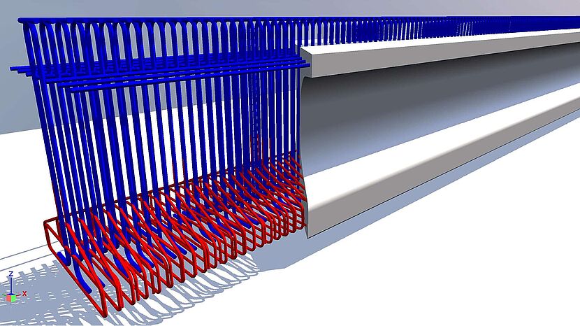
3.1 REINFORCEMENT DETAILING
The integrated parametric reinforcement modeling solution enhances workflows, productivity, and precision. Users can easily create parametric BIM models with reinforcement, automatically linked to ALLPLAN Python Parts technology. This integration supports reinforcement design & code checks in ALLPLAN Civil, and simultaneously automatic generation of 3D reinforcement models in ALLPLAN.

3.2 FINAL PROOF CHECKING
The parametric reinforcement connection is bidirectional. The reinforcement area, adjustable through stirrup spacing and the number of longitudinal bars, can be re-imported into structural analysis for final code checking.

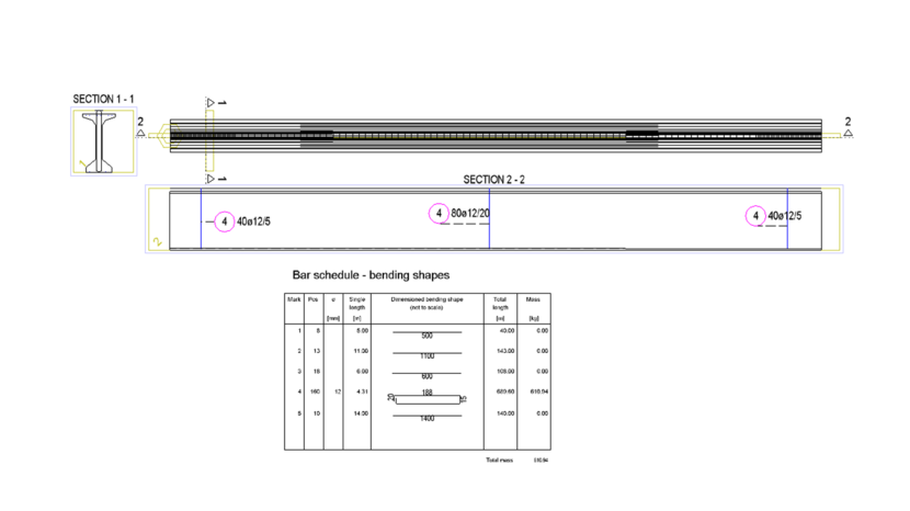

3.3 DRAWING GENERATION AND OTHER DELIVERABLES
Elevations, longitudinal sections along any path and transverse sections are derived from the digital 3D BIM model. CineRender from Maxon is used for realistic visualizations and ALLPLAN’s powerful layout and design tools are used to create high-quality construction documentation.
3.4 AUTOMATION - Reinforcement templates
No more tedious remodeling of reinforcement! Once a cross section is defined and all the necessary reinforcements are set. This cross section can be used as a template which can be used in a project or across projects. The variables that control the cross section also control the reinforcement. Thus, a complete reinforcement of the structure can be created by adjusting the variables. In cases where the complete reinforcement of a structure has to be custom created (independent of the geometry), a PythonPart template can be prepared and used as a placement at the requested positions.
Learn more
Our Offering