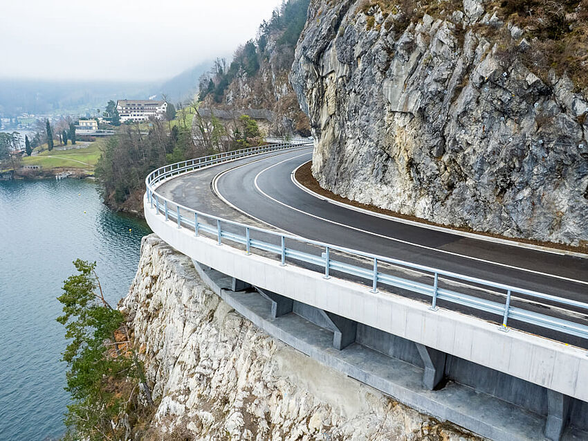
Above the lake: how parametric modeling delivered Lake Lucerne’s K2b road widening
Complex bridge projects rarely fit neatly within the capabilities of a single design tool. When geometry, structural requirements, fabrication constraints, and construction all interact, the challenge is creating a workflow that can manage that complexity without losing accuracy along the way. For two urban flyovers with challenging composite steel and concrete structures, Hungarian engineering firm CEH Planning, Developing and Consulting Ltd. combined the parametric capabilities of ALLPLAN Civil with specialist steel detailing tools to create an adaptable workflow from design to fabrication.
In summary: > Complex geometry and a changing road alignment led CEH to move beyond traditional 2D methods and develop a parametric bridge design workflow. > ALLPLAN Civil provided the geometric foundation for two composite flyovers, including a particularly challenging Y-shaped bifurcation with changing crossfalls. > The workflow connected parametric bridge design with specialist steel detailing, allowing the right tools to be used at different stages toward fabrication. > Fabrication, transportation, and assembly requirements added another layer of complexity, including container-sized components and fully bolted site connections. > Through the two projects, CEH identified practical lessons about parametric modeling – including when greater model detail adds value and when it simply adds work. |
When 2D design was no longer enough
One of the two flyovers presented a particularly demanding geometric challenge. Here, a three-lane carriageway transitioned into a two-plus-one-lane arrangement at a Y-shaped bifurcation, with changing crossfalls and main girders connecting across the split. The span arrangement added further structural complexity.
The challenge was compounded by the design program. The road alignment was not yet finalized, which, combined with a tight deadline, meant that managing the complete bridge geometry using a traditional 2D approach would be neither fast nor reliable enough.
CEH initially developed key cross-sections in AutoCAD for conceptual work and checking. However, managing the complete geometry reliably required a parametric 3D approach, which is why ALLPLAN Civil was chosen. The value of this decision became clear when the road alignment changed relatively late in the design. Rather than manually redrafting significant parts of the bridge, CEH could update the main geometry within the parametric ALLPLAN Civil model in a controlled way.
Building a parametric foundation in ALLPLAN Civil
CEH modeled both the superstructure and substructure parametrically in ALLPLAN Civil, incorporating the complex piers, cross-girder spacing, crossfall transitions, and separate bridge sections converging at the Y-shaped bifurcation. Despite the challenging geometry, the sections achieved an accurate fit, while data could be extracted with millimeter-level precision at practically any point.
Multiple cross-sections also allowed CEH to check diaphragm positions, bolted connection areas, and characteristic points on the main girders. The model therefore provided more than a 3D representation of the bridge; it also established a reliable geometric foundation for the engineering and detailing work that followed.
Developing a steel fabrication workflow
For the detailed steel fabrication model, CEH moved the design into Tekla Structures. An initial IFC transfer preserved the geometry, but the imported components appeared as ITEMs rather than native Tekla steel elements, preventing them from being used directly for detailed fabrication modeling.
Instead, CEH extracted geometric points from the ALLPLAN model and used these to rebuild the steel structure in Tekla. Points were taken at element ends, intermediate locations, and extensions beyond the ends, providing the information required to cut and fit the steel elements accurately.
This gave each platform a clearly defined role: ALLPLAN Civil established and controlled the complex parametric geometry, while Tekla provided the specialist environment for detailed steel fabrication modeling. Rather than expecting one tool to handle every task, CEH transferred the information needed for each stage of the workflow.
Designing for transportation and construction
The workflow also had to account for how the steel structure would ultimately be fabricated, transported, and assembled. The steelwork was produced in Hungary before being transported to the overseas construction site, creating strict limits on the size of individual components. CEH therefore adapted the maximum component dimensions to fit within a standard 40-foot intermodal container.
The client also required the structure to be assembled on site without welding. As a result, all site connections were designed as bolted connections. These practical constraints added another layer of complexity to the bridge design and demonstrate why accurate geometric information was so important – the digital workflow had to support a steel structure that could be fabricated, transported, and assembled as planned.
Modeling the bridge before and after precamber
Another important part of CEH’s workflow was accounting for precamber. The team typically created two models: one representing the final designed state and another representing the precambered geometry required for fabrication.
ALLPLAN Civil simplified this process. By adding the camber diagram to the vertical alignment, CEH could quickly generate the precambered model and extract the required geometric data from it. This provided the team with accurate information for both states without having to recreate the bridge geometry manually. This was another practical benefit of establishing the design parametrically from the outset.
Model what you need, not everything you can
CEH’s experience with the smaller flyover provided another valuable lesson: greater model detail does not always mean a more efficient workflow. As the first of the two bridges to progress through design, it became a prototype for developing the parametric approach. CEH created a highly detailed ALLPLAN Civil model, with separate cross-sections for elements such as diaphragms and cross-girder webs and flanges.
While this produced an accurate model that was useful for visualization and checking the steel design, it also required significant manual effort. For the more complex flyover, CEH could therefore take a more targeted approach of developing the parametric model to the level needed to provide reliable geometry, while leaving finer steel details to the specialist fabrication environment.
The lesson was simple: the most effective model is not necessarily the most detailed one, but the one developed to the right level for its intended purpose.
Connecting complex bridge design to fabrication
CEH’s experience demonstrates that complex composite bridge design does not necessarily require one tool to handle every task. Instead, an effective workflow depends on understanding what each platform does best and defining how information will move between them.
By establishing these roles from the outset – and modeling each stage to the level of detail it actually required – CEH created a practical workflow capable of taking challenging bridge geometry closer to fabrication and construction.